MUT BIOMASS
TM 2000
FOR CENTRAL HEATING SYSTEMS
MAIN CHARACTERISTICS
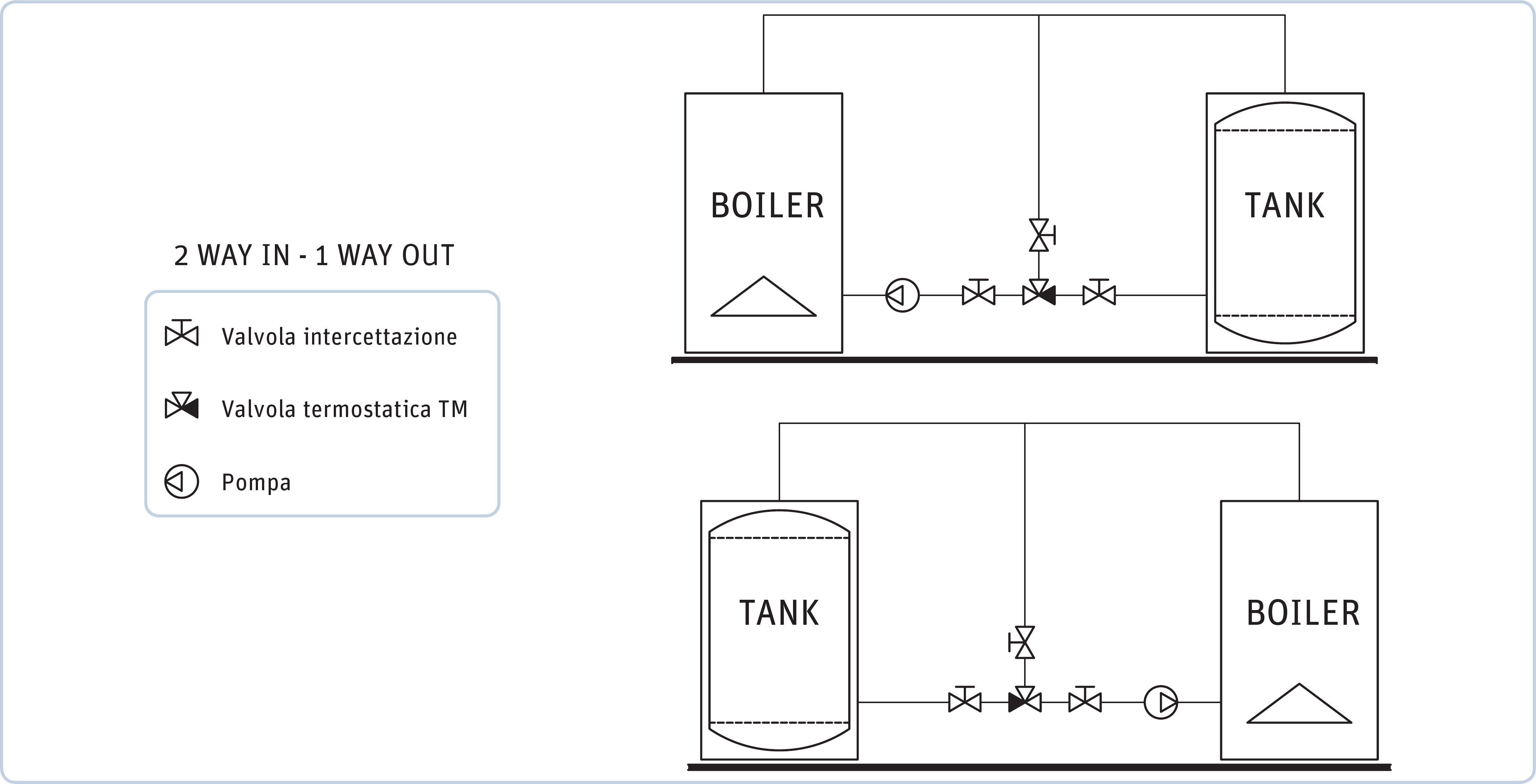
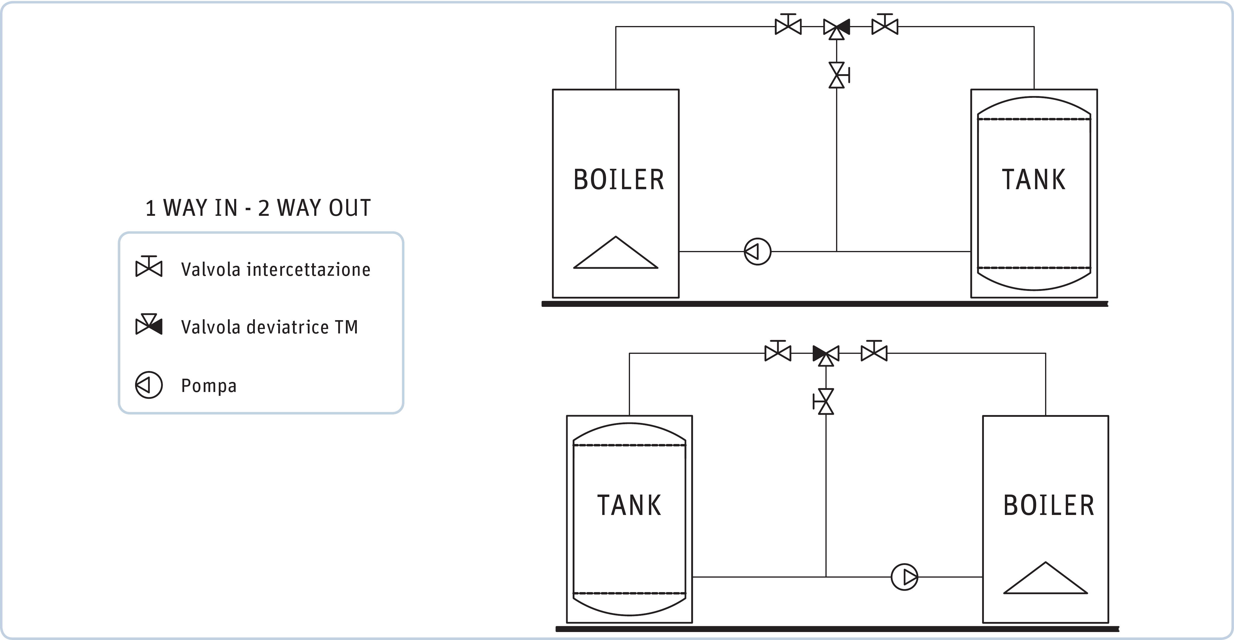
TM 2000 mixer valves find application in those heating systems (systems with solid fuel boiler and storage tank) where it is essential to ensure the return of hot water (at a minimum temperature level) to the boiler, thus ensuring a sufficiently high thermal regime of operation to prevent vapour condensation in the smokestack.
These vapours combined with the products of combustion may give rise to corrosive compounds that affect and limit the life of the boiler.


With the use of the valves TM 2000 are obtained the following advantages:
- Increasing the combustion efficiency of the heat generator.
- Avoiding the risk of destructive thermal shock.
- Significant lengthening of the working life of the boiler.
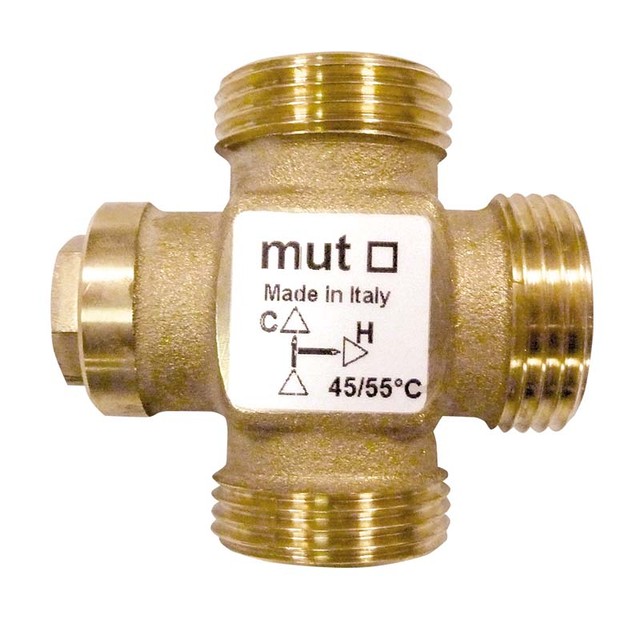
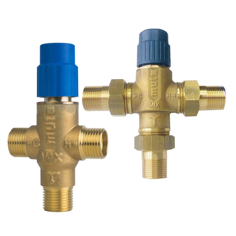
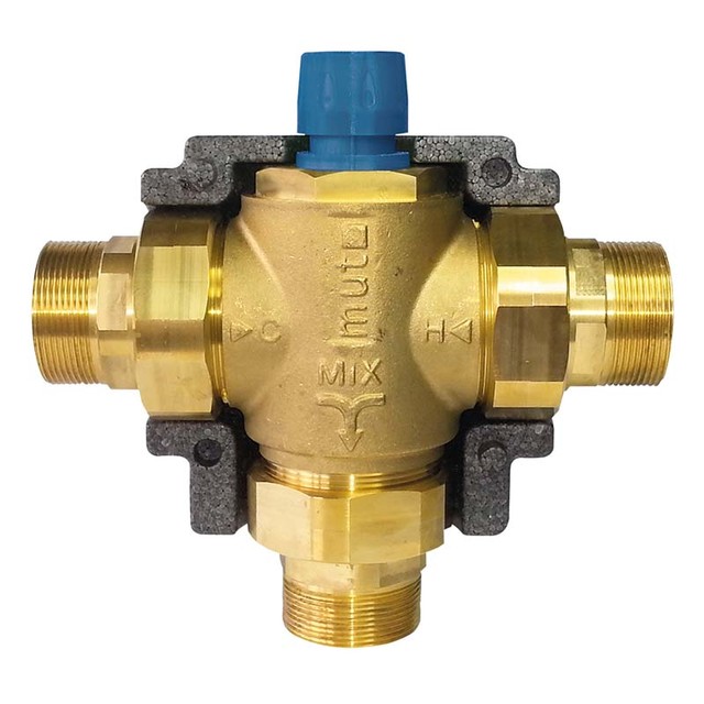
The thermostatic mixing valve TM 2000 aren’t equipped with electrical / electronic devices, with consequently great benefit of reliability and simplicity of system installation and maintenance. The “one single piece” thermostat-lid allows a quick and easy replacement of the thermostat. To ensure accurate precision, the thermostatic sensor is immersed directly into the fluid. Operation temperature range: 5 -110 ° C. Maximum operating pressure:10 bar. TM 2000 mixer valves are available in 4 sizes (G ¾, “G 1”, G 1 ¼”, G 1 ½”) .
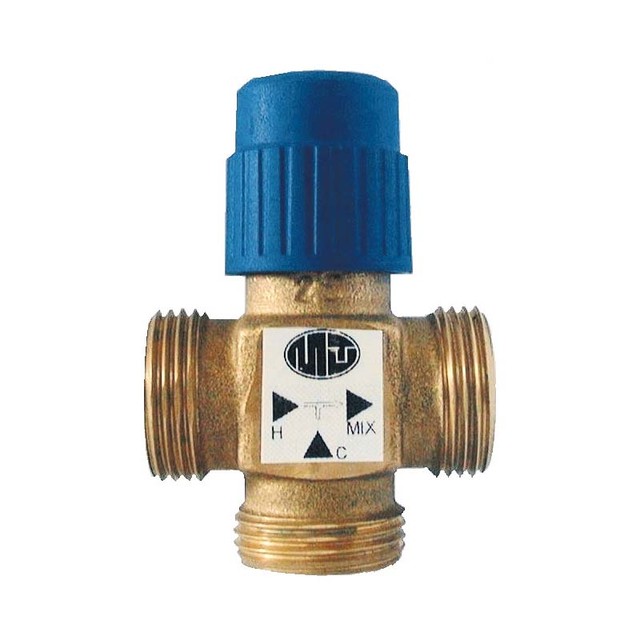
The thermostatic sensor is immersed directly in the fluid. According to the temperature value set (temperature settings available – standard version: 45 – 50 – 55 – 62 – 72 - 78 °C), the valve mixes the fluid flows so that the fluid flow returning to boiler is always at the right set-point temperature. On specific request, TM 2000 mixer valve may be supplied with temperature set values different from those of the standard valve set.
- Valve body: Cast Iron GJL220
- Thermostatic cartridge: Die-cast aluminium AB 46100 Al Si 11 Cu 2
- Spring: Steel AISI 302 EN 10204-3.1
Type of action
Manual

Nominal pressure
Max 10 bar

Fluid temperature limits
5 ÷ 110 °C [max]

Max. ambient temperature
-

Range of Temperature’s set available
45 °C ÷ 50 °C ÷ 55 °C ÷ 63 °C ÷ 72 °C ÷ 78 °C

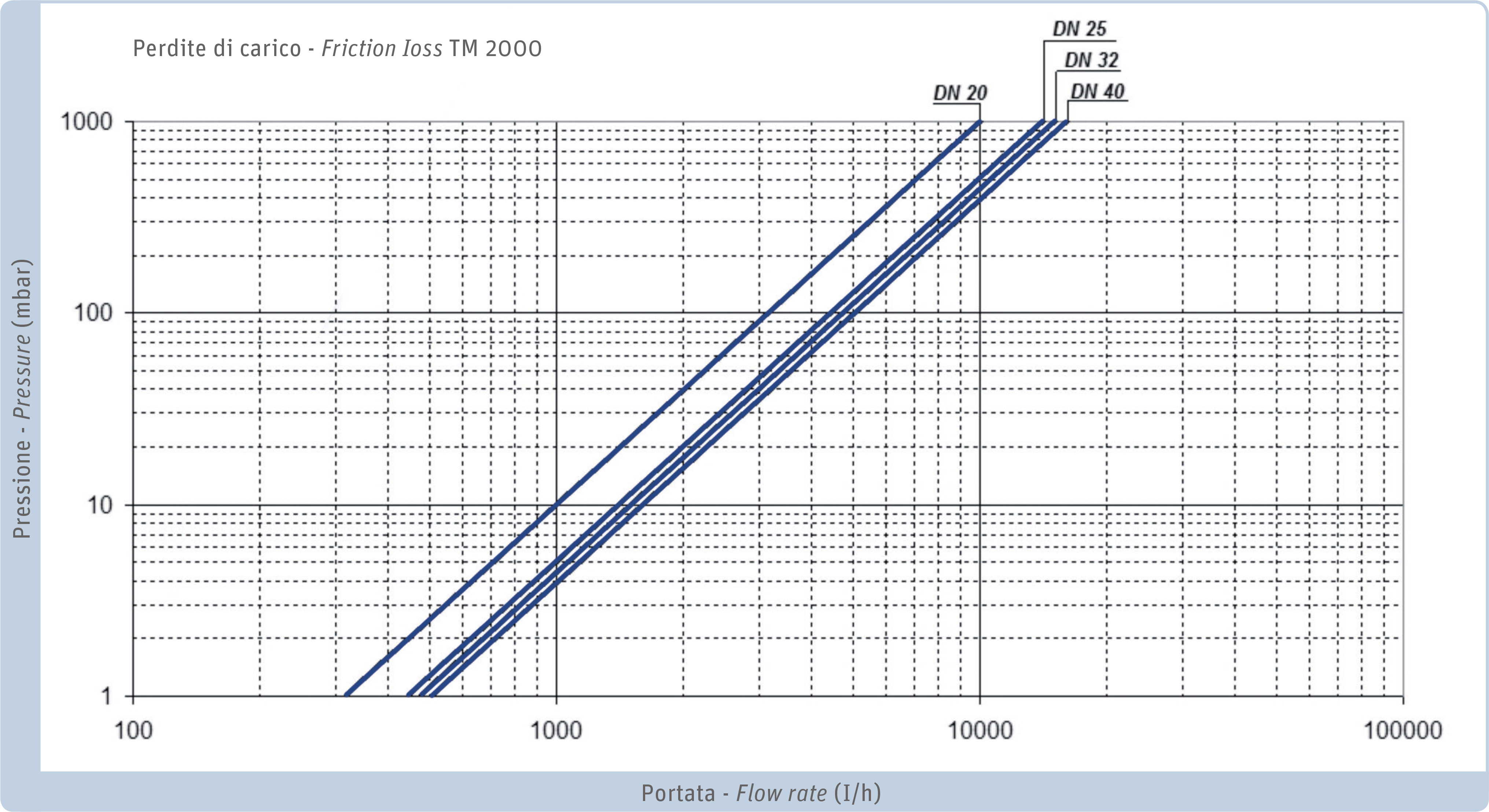
Capacity coefficient Kvs
G ¾” : 10 m3/h - G 1” : 14 m3/hG 1 ¼” : 15 m3/h - G 1 ½ ” : 16 m3/h (m³/h - ΔP =1 bar)
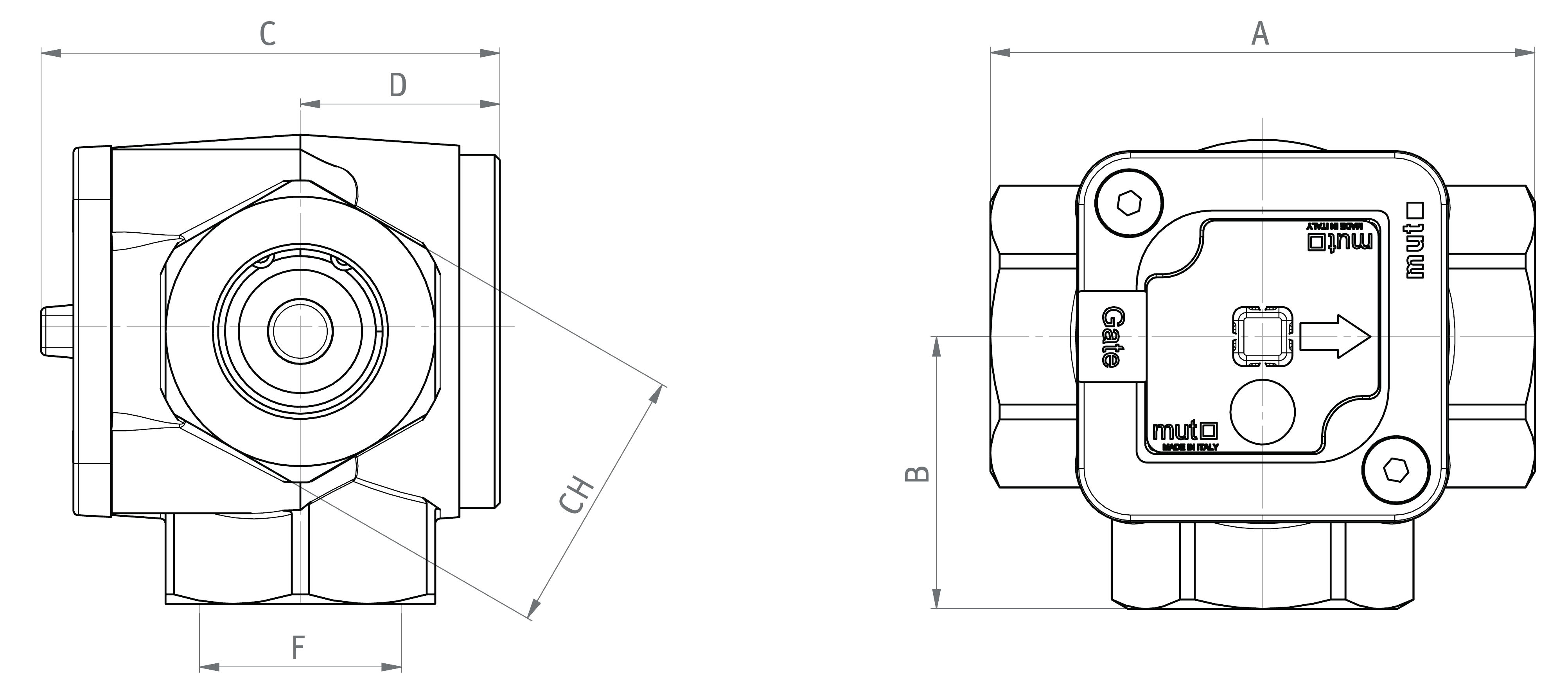
| DN | ISO 228 | A | B | C | D | F | CH |
|---|---|---|---|---|---|---|---|
| 20 | G ¾ | 100 | 50 | 37 | 84 | G ¾ | 45 |
| 25 | G 1 | 100 | 50 | 37 | 84 | G 1 | 50 |
| 32 | G1 ¼ | 110 | 50 | 37 | 84 | G1 ¼ | 60 |
| 40 | G1 ½ | 120 | 60 | 37 | 84 | G1 ¼ | 65 |
| Type | DN | Ø UNI ISO 228 | Kvs m³/h | temperature °C |
|---|---|---|---|---|
| TM | 20 | G ¾ | 10 | 45 ° - 50 ° - 55 ° - 63 ° - 72 ° - 78 ° |
| TM | 25 | G1 | 14 | 45 ° - 50 ° - 55 ° - 63 ° - 72 ° - 78 ° |
| TM | 32 | G1 ¼ | 15 | 45 ° - 50 ° - 55 ° - 63 ° - 72 ° - 78 ° |
| TM | 40 | G1 ½ | 16 | 45 ° - 50 ° - 55 ° - 63 ° - 72 ° - 78 ° |
INSTRUCTIONS
WARNING! BEFORE CARRYING OUT ANY OPERATION
- Make sure the pump is off.
- Close the three-way ball valves and discharge the system.
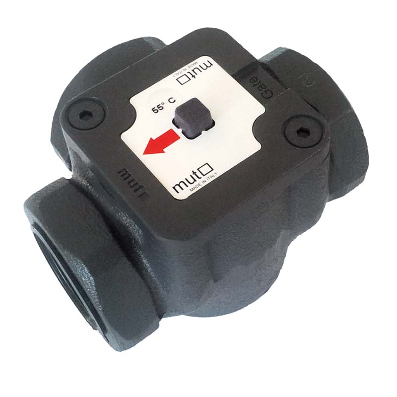
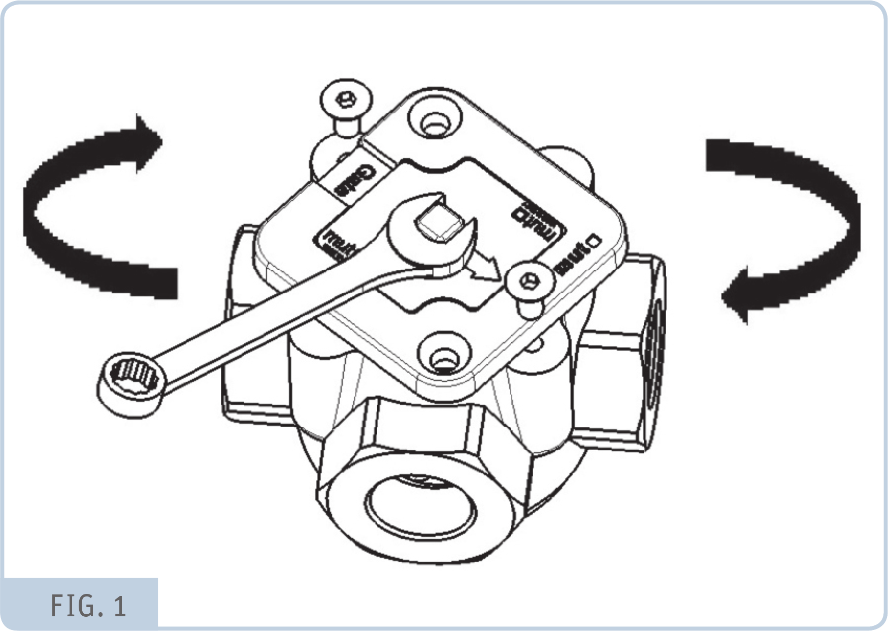
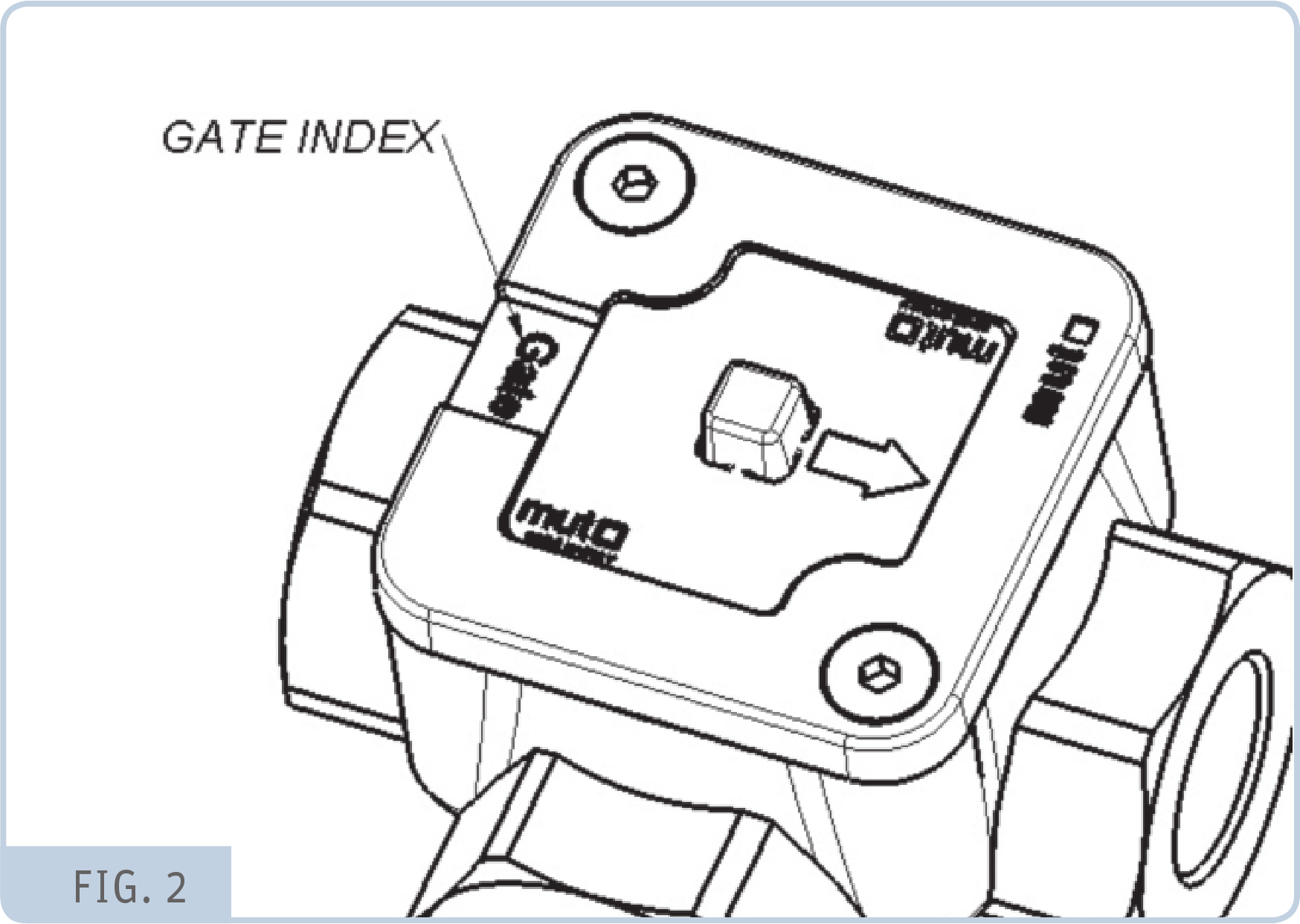
The valve can be fitted in any position. To reproduce the sample circuits shown after, refer to the “Gate” see fig. 2
- Switch off the pump
- Close the three-way ball valves
- Completely unscrew the two screws on the TM 2000 cartridge lid
- Using a Ch 10 wrench, rotate the lid and take the gate to the required position
- Return the 2 screws to their original position and tighten
- Open the three ball valves and recharge the system if necessary
- The system is now ready to use
- Switch on the pump.
-
REPLACING THE THERMOSTAT
- Switch off the pump
- Close the three-way ball valves
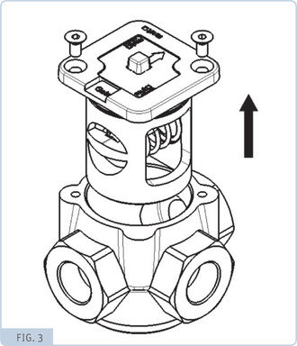
- Completely unscrew the two screws on the TM 2000 cartridge lid
- Remove the TM 2000 cartridge lid
- Position the new cartridge lid with the required thermostat
- Tighten the two screws
- Open the three ball valves and recharge the system if necessary
- The system is now ready to use 9 - Switch on the pump.

TM2000
Adjustable thermostatic mixer valve for centralised heating systems ( also for thermal solar and biomass fuel systems), MUT series TM 2000. To apply when it is essential to ensure the return of hot water (at a minimum temperature level) to the boiler , thus ensuring a sufficiently high thermal regime of operation to prevent vapour condensation in the smoke- stack. Threaded connections: G ¾” , G 1” , G 1 ¼”, G 1 ½”F. Monolithic cartridge lid (one single piece). Valve body material: Cast Iron GJL200; thermostatic cartridge lid material: Die-cast aluminium AB 46100 Al Si 11 Cu ; Spring: Stainless Steel AISI 302 EN 10204-3.1. The thermostatic sensor is immersed directly into the fluid. Fluid’s temperature limits 5 ÷ 110 °C. Nominal pressure: PN 10 bar. Range of mixed water Temperature’s adjustment available: 45 °C ÷ 50 °C ÷ 55 °C ÷ 63 °C ÷ 72 °C ÷ 78 °C .
| TM2000 Datasheet | 2014-03-06 | it, en | go |
-
RA
-
RAJ
-
RAW
-
VTD